Fitting a Triangulation to Contour Lines
4.5 (157) In stock

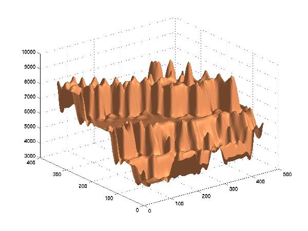
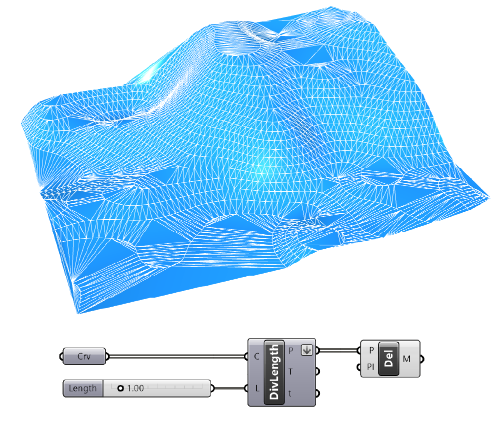
This paper presents a technique for creating a triangle mesh that tightly fits a terrain surface represented by a set of digitized contour lines and the advantages of using this mesh rather than the well known Delaunay triangulation for computing a gridded Digital Terrain Model (DTM). This paper presents a technique for creating a triangle mesh that tightly fits a terrain surface represented by a set of digitized contour lines. Basic to the technique is a Medial Axis transformation of a polygon, in this case formed by one or more contour lines. The advantages of using this mesh rather than the well known Delaunay triangulation for computing a gridded Digital Terrain Model (DTM) are discussed, as well as widely used spline interpolation methods. An example illustrates how the Medial Axis relates to the polygon and triangles and thereby facilitates further adjustments to the mesh. More complex adjustments to convert the triangulation into a surface devoid of unnatural features are described. Anomaly-free DTMs can be computed from contours without the supplementary features demanded by interpolation and triangulation procedures in use today. Desk-top computer programs operating on a small area of a scanned contour plate were prepared to test and illustrate the procedures that are outlined. TWO CONTOUR-TO-G-RID METHODS Converting a given set of contours into a gridded numerical model of elevations, commonly called a Digital Terrain Model (DTM), can be accomplished by two widely different approaches. Interpolation Method. The better known approach that is called here the 'Interpolation 1 method consists of the following: Vertical planes passing through each grid point intersect the source contours. Straight lines or planar curves contained in the vertical planes are defined by the intersections, and used to interpolate elevations at the corresponding grid point. There are numerous reports on implementation of this approach and on the nature of the curves used in the process. See references in [8,9]. Triangulation Method. The second, less known method, is called the 'Triangulation 1 method. The triangulation that constitutes the chief component for converting from contours to grid is performed by an algorithm that selects part or all the points in the source contours and establishes with them a mesh of non-overlapping triangles. From these triangles grid values are computed. THE DIM IN BETWEEN SOURCE CONTOURS Before discussing the problems found in interpolated DTMs, the subject of how the DTM is expected to behave in areas devoid of sampling should be examined. Obviously, the replication of source contours from the DTM should be a concern, although by no means the

Approximating Complex Surfaces by Triangulation of Contour Lines
Terrain Elevation Data Structure Operations

Contouring and Visualization of Data.

vtkContourTriangulator (Triangulation failed) - Development - VTK

Triangulation of the unit circle with N = 16 elements along the radius

Report, PDF, Topography
How to generate a surface from points in Grasshopper - Hopific

Analist 2015: Model Triangulation, Contour Lines and Land Profile

Contour map of the chosen channel's head. Contour interval is 1.5 m. We
The portion of triangulation that can be elongated without changing the
Contouring Your Nose – Beauty Blurbs & Babbles
How To Highlight & Contour For Your Face Shape » Read Now!
Triangle strip created to represent a contour line. The triangles
Adjust Flat Triangle Setting - Surface Modeling Work Processes
 High Intensity Fully Adjustable PowerFlex Sports Bra with Zip and Moul
 Nike Girls Black Sweatpants Joggers Draw String Pockets Black & Pink Size Small
 Suitop men's sexy rubber latex leggings with crotch zipper in black color
 Sun Ringle rim Mulefut 80 27.5 32H for fat bike
 How does Pilates Reformer compare to resistance band training for shap
 Best Buy Canada to Open its Doors Early for Black Friday